Calibrating the measuring tool
The following tasks should be performed only by well-trained and qualified persons. The legalities with regard to performing an accuracy check or calibration of a measuring tool must be known.
- Perform calibration of the measuring tool with extreme precision or have the measuring tool checked by a Bosch customer service agent. Inaccurate calibration leads to incorrect measuring results.
- Only start the calibration if you have to perform a calibration of the measuring tool. As soon as the measuring tool is in calibration mode, you must perform the calibration meticulously to the end in order to ensure that no incorrect measuring results are produced afterwards.
Check the levelling accuracy after every calibration see Accuracy Check of the Measuring Tool. If the deviation is outside the maximum permitted limits, have the measuring tool checked by a Bosch customer service agent.
Always calibrate all axes (X-axis, Y-axis and Z-axis).
Note: If the X-axis (7) or Y-axis (6) status indicator flashes red during calibration, this indicates that the deviation is outside the maximum permitted range. If this is the case, press the manual operation button (14) to exit calibration mode without saving the settings. The X-axis (7) and Y-axis (6) status indicators will ten flash red at 3×/s to indicate calibration errors.
Restart the calibration. If the error occurs again, have the measuring tool checked by a Bosch customer service agent.
X-axis and Y-axis Calibration
For calibration, you will need a free measuring distance of 30 m on firm ground in front of a wall.
If required (e.g. in poor lighting conditions), you can use a laser receiver (37) to mark the laser beam. When using the laser receiver, take care that it is aligned vertically on the wall, as otherwise the marks are offset with respect to the laser beam. With laser receivers with an adjustable reception accuracy, you can set the reception accuracy depending on the required calibration accuracy (see the operating instructions for the laser receiver).
Mounting and aligning the measuring tool for calibration:
Mount the measuring tool in the horizontal position 30 m from the wall on the tripod (39) (recommended) or position it on a firm, level surface.
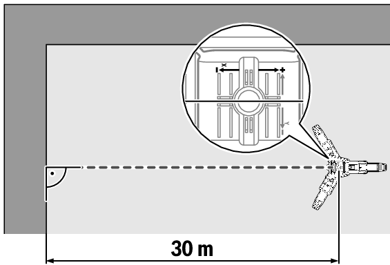
Align the measuring tool so that the X-axis indicator imprinted on the measuring tool is at right angles to the wall.
Starting calibration:
The measuring tool must be switched off when calibration starts.
Press and hold the manual operation button (14) on the measuring tool and then also briefly press the on/off button (3). Release the manual operation button only when the X‑axis status indicator (7) flashes green and the shock-warning function indicator (13) flashes red (both at 2×/s).
The measuring tool is switched on in calibration mode for the X‑axis.
X-axis calibration:
Ensure that the measuring tool is aligned with the X‑axis at right angles to the wall. Wait until the measuring tool is levelled in and rotational operation has started.
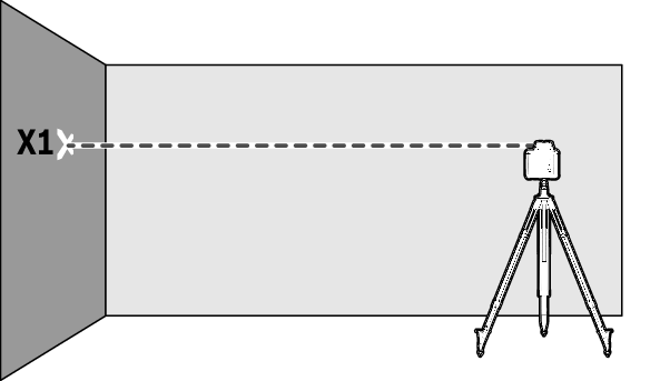
Mark the height of the laser beam on the wall as height X1. To do this, you may need to use the laser receiver (37).
Turn the measuring tool through 180° without adjusting the height and position of the measuring tool.
Wait until the measuring tool is levelled in and rotational operation has started.
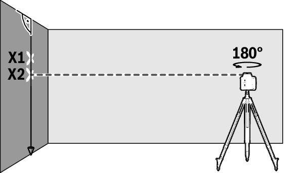
Mark the height of the laser beam on the wall as height X2. To do this, you may need to use the laser receiver (37). Note that height X2 should preferably be positioned vertically above or below height X1.
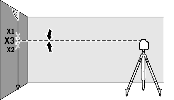
Determine the exact centre point between the marked heights X1 and X2 and mark this on the wall as height X3.
Align the variable laser beam (8) using the down (5) and up (15) slope buttons so that it hits height X3 as accurately as possible. To do this, you may need to use the laser receiver (37).
Save the calibration of the X-axis by pressing the manual operation button (14). As confirmation, the X-axis status indicator (7) will flash green six times.
Y-axis calibration:
After calibration of the X‑axis, the measuring tool automatically switches to calibration mode for the Y‑axis. The Y‑axis status indicator (6) flashes green and the shock-warning function indicator (13) flashes red (both at 2×/s).
Turn the measuring tool through 90° so that the Y-axis indicator imprinted on the measuring tool is at right angles to the wall. Then calibrate as described for the X‑axis.
If the calibration of the Y-axis has been saved, the Y‑axis status indicator (6) will flash green six times. Calibration mode will be ended automatically.
Z-axis Calibration
A free measuring distance on firm ground in front of a 10 m wall is required for the calibration. Fix a plumb line to the wall.
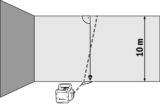
Position the measuring tool in a vertical position on a firm, level surface. Switch the measuring tool on and allow it to level in. Align the measuring tool so that the variable laser beam contacts the wall at right angles and cuts through the plumb line. Switch the measuring tool off.
To start calibration mode, press and hold the manual operation button (14) and then also briefly press the on/off button (3). Release the manual operation button only when the X‑axis status indicator (7) flashes green and the shock-warning function indicator (13) flashes red (both at 2×/s).
The measuring tool is switched on in calibration mode for the Z‑axis. Wait until the measuring tool is levelled in and rotational operation has started.
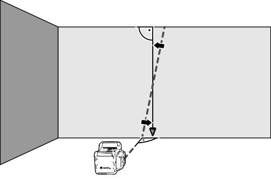
Align the variable laser beam so that it runs as parallel as possible to the plumb line. To do this, press the down (5) or up (15) slope buttons.
If it is not possible to align the laser beam in parallel to the plumb line, align the measuring tool to the wall more precisely and start the calibration process again.
If the laser beam is aligned in parallel, save the calibration by pressing the manual operation button (14). As confirmation, the X-axis status indicator (7) will flash green six times.
The calibration of the Z‑axis will be saved and calibration mode automatically ended.

